40 Gigabit Ethernet Cabling Solutions With MPO Technology
The increasing demands of bandwidth and high speed drive the emergence of 40 GbE. MPO technology with multifiber connectors offers ideal conditions for setting up high-performance data networks in data centers to achieve greater bandwidth and handle future requirements. This technology makes scaling and migration to network operation with 40/100 Gigabit Ethernet all the easier and more efficient. This article will introduce the practical application of MPO technology, which shows the solutions for 40 Gigabit Ethernet.
MPO connector (multi-fiber push-on and also as multi-path push-on) is a multi-fiber connector defined according to IEC 61754-7 and TIA/EIA 604-5. It is the main component in MPO technology that can accommodate up to 72 fibers in the tiniest of spaces, comparable to an RJ45 connector. MPO connectors are most commonly used for 12 or 24 fibers. In order to provide an introduction and basic information to the reader, this section begins with a presentation of the components needed for a parallel optical MPO connection. The MPO connectors can contact up to 72 fibers in a single connection. A connection must be stable and its ends correctly aligned, which is essential for achieving the required transmission parameters. A defective connection may even damage components and cause the link to fail altogether.
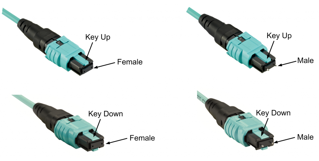
MPO connectors are available in a female version or a male version (with pins) as shown in the following picture. The pins ensure the exact alignment of the fronts of the connectors, and also they ensure the end faces of the fibers are not offset.

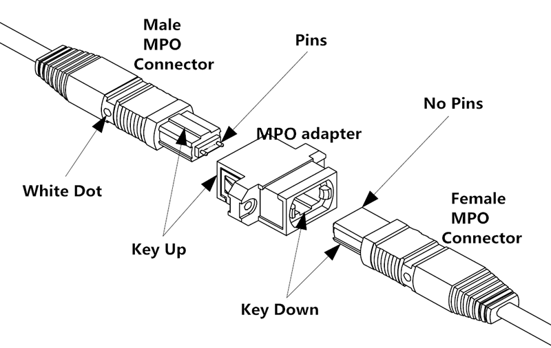
Noses and guide grooves on the top side are the two other clearly visible features, which ensures the adapter hold the connector with the correct ends aligned with each other. Based on the placement of the key, two types of MPO adapters are available. One is “key-up to key-down”. It means the key is up on one side and down on the other. The two connectors are connected turned 180° in relation to each other. The other one is “key-up to key-up”. It means both keys are up. The two connectors are connected while in the same position in relation to each other.
Always use one male connector and one female connector plus one MPO adapter when creating a MPO connection (see the following picture).

Never connect a female to a female or a male to a male. It should be connected with a male and a female as stated above. With a female-to-female connection, the fiber cores of the two connectors will not be at the exact same height because the guide pins are missing. That will lead to losses in performance. A male-to-male connection has even more disastrous results. There the guide pins hit against guide pins so no contact is established. This can also damage the connectors.
Never dismantle a MPO connector. The pins are difficult to detach from a MPO connector and the fibers might break in the process. In addition, the warranty becomes null and void if you open the connector housing.
MPO cable has the advantages of shorter installation times, tested and guaranteed quality and greater reliability. It has several different kinds of types.
MPO trunk cable with two MPO connectors (male/female) on both end of the cable serves as a permanent link connecting the MPO modules to each other, which is available with 12, 24, 48, 72 fibers. MPO trunk cable requires greater care in planning but has a number of advantages, such as higher quality, minimal skew, shorter installation time, better protection, smaller volume of cable and lower total costs.
MPO harness cable is terminated with a male/female connector on the MPO side and several duplex LC/SC connectors on the other side. MPO harness cable provides a transition from multi-fiber cables to individual fibers or duplex connectors. For example, 8 fibers 12 strands MPO harness cable has eight LC high fiber density connectors and a MPO connector, which is convenient for wiring and management system in 40G network with stable performance.
OM3 and OM4 fiber optic cables put in a parallel optical connection, terminated with MPO/MTP connectors. These are the ingredients for 40 GbE technology in a structured cabling environment. Parallel optical channels with multifiber multimode optical fibers of the categories OM3 and OM4 are used for implementing 40 GbE. The small diameter of the optical fibers poses no problems in laying the lines, but the ports suddenly have to accommodate four or even ten times the number of connectors. This large number of connectors can no longer be covered with conventional individual connectors. So the 802.3ba standard incorporated the MPO connector for 40GBASE-SR4.
MPO connectors and cables are the core components of a 40G parallel optical link. The connecting link determines whether the insertion loss exceeds the attenuation budget and whether the return loss is high enough. In the end, the desired bandwidth can only be reached if all components in a parallel optical link satisfy the highest requirements.